
A single-wire diagram is essential when installing a new electrical system. But what exactly does it entail? And how can you draw such a single-wire diagram? Here is all the info and a clear step-by-step plan from a to z.
A one-wire diagram, what is that anyway?
A single-wire electrical diagram is a valuable tool for anyone involved in the design, installation and maintenance of residential electrical systems. Specifically, this electrical schematic provides a clear picture of the electrical circuits, light points, switches and other elements that make up the electrical infrastructure.
AREI and the single wire diagram
This is not an unnecessary luxury, as any licensed electrical engineer knows. Because a well-designed single-wire diagram ensures that the entire electrical installation is safe and reliable and complies with building standards.Indeed, it is important that the diagram complies with the guidelines of the General Regulations on Electrical Installations (AREI). This is applicable in Belgium and contains technical requirements, procedures and provisions for the installation and safety of electrical installations in buildings.
Duck wire diagram symbols
Duck wire diagrams are characterized by the electrical symbols. They represent the different components of an electrical installation.For example, changeover switches, double-pole switches, cross switches and sockets each have a separate, specific symbol. The table below summarizes the most common symbols.

No one-wire diagram without a situation diagram
The single-wire diagram usually goes hand in hand with a situation diagram. You usually have to submit both when inspecting the installation. The difference between the two? The single-wire diagram helps plan the power paths, while the situation diagram shows the locations of the various elements in the electrical installation. So you know where outlets, switches, push buttons, and lights should be placed. Or, for example, junction boxes, ground interrupters, and other utility equipment. All these components are shown in a situation diagram on the floor plan of the house. This makes the installation as safe as it is efficient.
Example: single wire diagram in practice
Below is a one-wire diagram as an example.
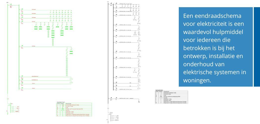
Stabicad Duck wire diagram
How to draw a one-wire diagram in five steps
And then comes the drawing of a single-wire diagram. The right software is a huge asset when drawing a single-wire diagram. If you draw a single-wire diagram via an approved tool, you typically go through the following steps:
Step 1: create a new project
Begin setting up a new electrical engineering project within your chosen BIM or CAD software. Import or integrate architectural underpinnings, such as detailed floor plans and architectural drawings, that represent the physical spaces and structural boundaries of the building. Set basic project settings, such as scale, units and layer management. This allows you to create a structured and coordinated working environment. This ensures that all further modeling and documentation is done within the correct context and in accordance with building standards.
Step 2: Model the main components of the electrical system
Start by modeling the main distributor and sub-distributors. This includes placing distributors and setting their characteristics such as location and connections.Continue modeling the essential components of the electrical system. Consider defining and placing the main distributor and any sub-distributors. These act as the central nodes for power distribution within the building. Include accurate specifications for each component, such as its size, location, and capacity. This will ensure an effective and safe electrical infrastructure. Draw the main power paths running from these distributors. Make sure these power paths are correctly planned to supply power to all parts of the building. And so you have laid the foundation for the further detailed design and placement of additional electrical elements. Such as circuits and terminal equipment.
Step 3: place electrical symbols and components
Then you place in detail all the necessary electrical symbols and components. Sockets, switches, light fixtures, and other end devices, that is. To do this, use the library of standard electrical symbols within your software. The way to ensure consistency and accuracy in the design. Make sure that each symbol is placed in the correct location according to the architectural underpinnings and technical specifications. Add relevant metadata to each symbol, such as connection type, load capacity, and controls. This is crucial for later phases such as circuit analysis and inspections. In short :in this step you visualize the complete electrical layout.
Step 4: connect and route wiring
Design the wiring between all the electrical components. You do this by making connections from the previously placed distributors to the outlets, switches, and lighting fixtures. Use tools for routing cables and wires within the software. This ensures that all paths are logical, efficient, and compliant with applicable standards and regulations.
Step 5: define and verify circuit information
Assign all components to specific circuits. Verify that each circuit is correctly configured for the expected load and meets safety standards. Set ampere ratings and check load calculations. This is an AREI rule to prevent overloading. This stage is critical to both the functionality and safety of the installation!
Step 6: Conduct a comprehensive review of the entire electric model
Use simulation and analysis functions within the software to evaluate electrical system performance and identify potential problems. Optimize where necessary by making adjustments to component selection, wiring diagrams, and the overall layout of the electrical system.
Step 7: document and export
Generate the necessary documentation from the model. For example, the detailed single wire diagrams, as well as bills of materials and installation reports. Afterwards, export the completed model and all documents to the appropriate formats. This way, all stakeholders (construction teams, customers, and inspection bodies) can consult and interpret them.
Draw a one-wire diagram using software?
The right MEP software is an enormous added value when drawing a single wire diagram. Within Stabicad, the electrical components library is fully aligned with Dutch, Belgian and European standards. The free Switch Range Configurator for Revit is another added value. This allows you to easily design complete switch ranges. Furthermore, Stabicad includes a module for electrical engineering calculations within Revit. This allows you to perform integrated calculations. To perform lighting calculations, Stabicad also offers a link to Dialux. Ideal for integrating and optimizing specialized lighting plans.
Want to know more? Feel free to contact us for a customized demo!


