About the project
Category: Infrastructure project Company: VIRY SA Project location: QUIMPER, France
The project in pictures
The project in figures
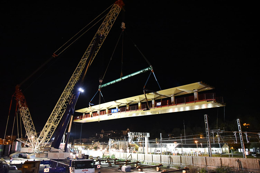
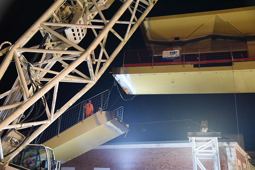
Length of footbridge: 86 metres A 4.5-metre-wide steel caisson for the deck and monumental staircases A 5.5-metre-wide diamond-point caisson for the roof Lifting of the central package by crane under catenary shutdown: 198 tonnes Total weight of steel structures: 300 tonnes Sheaths: 900 metres
Trimble products used
Tekla Structures Tekla Model Sharing Trimble Connect
Project description
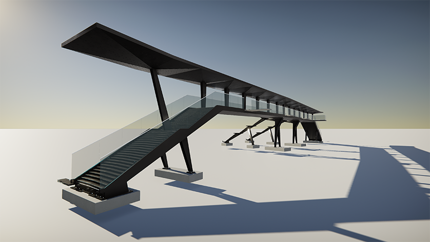
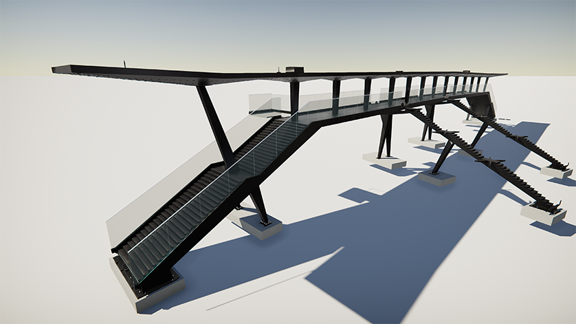
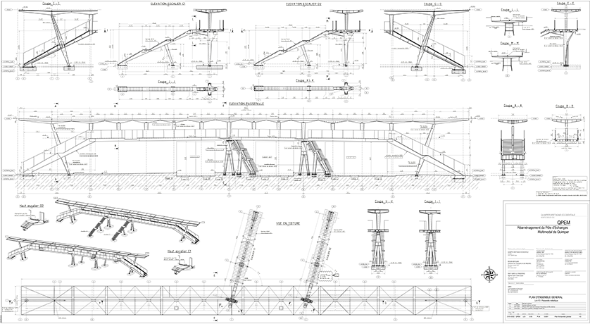
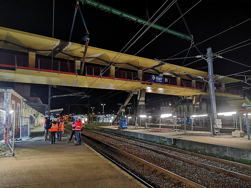
As part of the development of Quimper's Pôle d'Echange Multimodal (PEM), Viry, as GTM Ouest's co-contractor, is in charge of building the footbridge over the station's rail network.
The bridge is made up of :
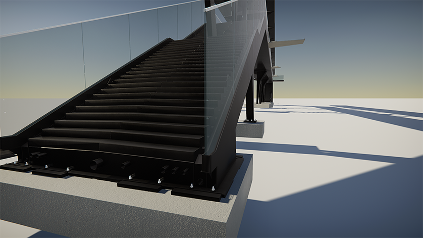
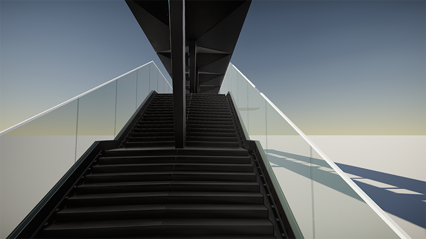
a metal box connecting 2 monumental staircases (one at each end),
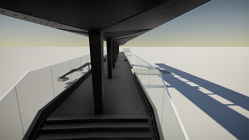
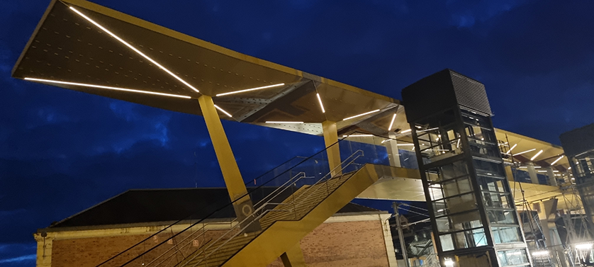
a roof in the shape of an inverted pyramid, connected to the deck via 14 columns, - 2 inverted-V piers,
2 dockside staircases also made of metal caisson.
To protect users of the footbridge, the structure is fitted with a glazed guardrail system embedded in the ground under site supervision.
The flush-mounted baseboard and associated accessories have been developed by our design office to meet the specifications of vertical catenary protection canopies.
This structure is designed to cross the railroad line and provide access to the platforms for pedestrians and SNCF users. The footbridge also carries numerous networks between the platforms through the deck, piers, posts, staircases and roof, providing lighting, power for screens, video surveillance, access to fiber optics, and the routing of EP and other services for the Quimper PEM.
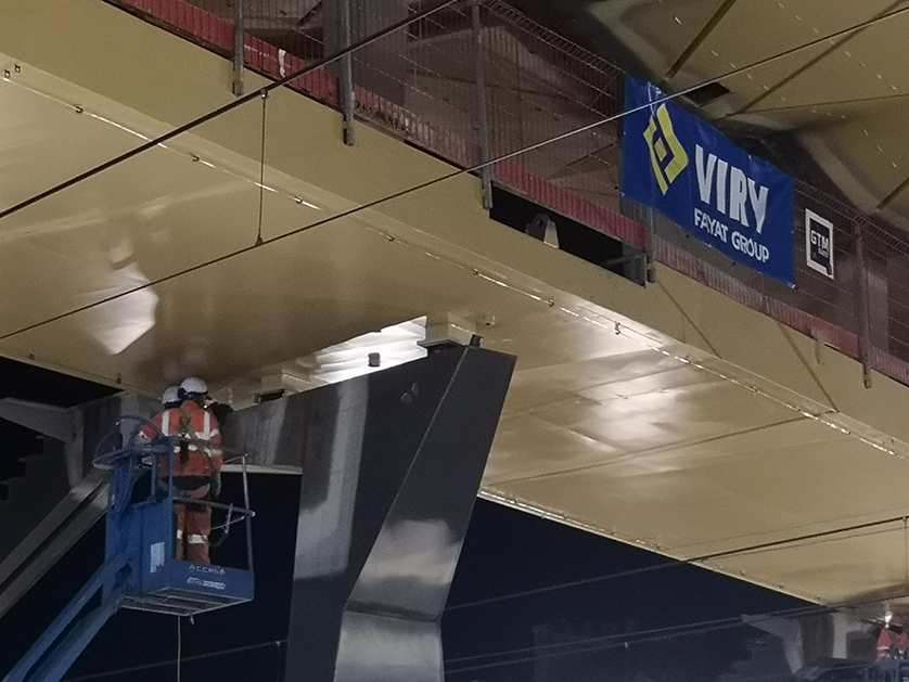
Blank assembly of the various sub-assemblies in the workshop, together with on-site geometric survey checks, enabled the frame to be easily installed and assembled on site, while guaranteeing perfect overall geometry.
This exceptionally large-scale project required a precise breakdown of the various components in order to take account of transport, handling and lifting constraints, both in the workshop and on site.
Challenges to meet
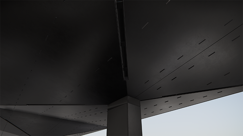
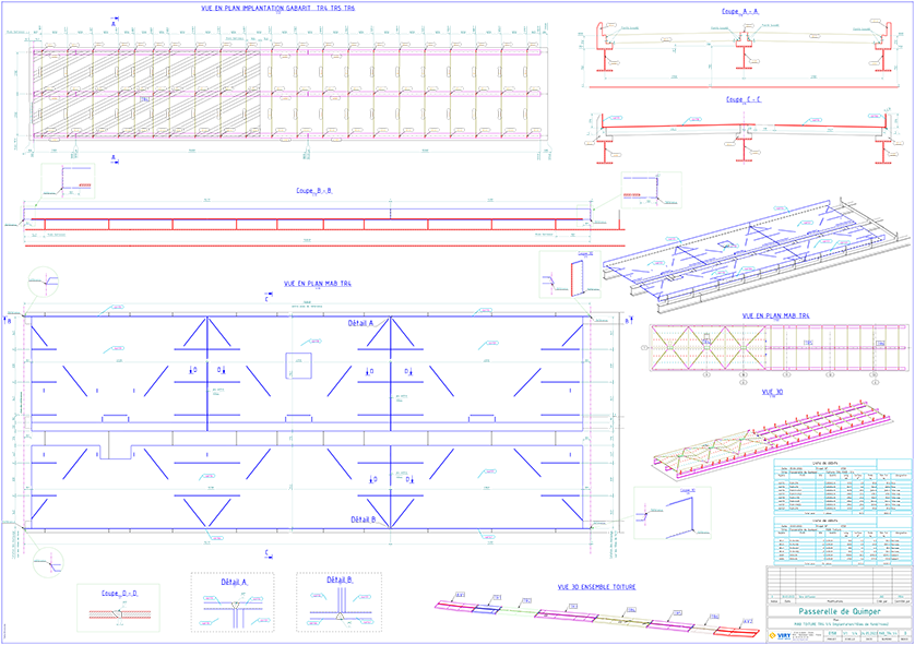
Modeling of 12 different roof modules and 2 non-symmetrical diamond-shaped end canopies, while respecting the regular layout of an architectural detail: overhanging "tenons" in parallel rows along the entire length of the ceiling.
The visible tenons on the underside of the roof (the ceiling for users) correspond to small protrusions (8mmx15mmx100mm) on the internal elements of the caisson (stiffeners), making assembly in the workshop more complex (interlocking of large-format parts on several dozen tenons) _[5.2mx2.6m to be fitted on 16 tenons _mark 4bt40// 6.4m x 2.7m to be fitted on 33 tenons_mark abt106).
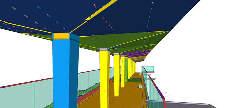
The internal routing of cable ducts in the box is a BIM subject in its own right, as it is the result of a synthesis between different work packages (electrical/CFO/CFA/fiber optics/joinery for the routing of power cables for motorized gates, handrail lighting cables/metal structure/VRD at ground level/metal framework to avoid highly stressed points, etc.).
Network routing is planned late in the process, whereas the location of stainless steel sheaths in the casing must be defined well in advance.
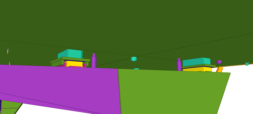
Workshop assembly kinematics were taken into account right from the modeling phase, to ensure that the chamfer orientation of the various markers was correctly taken into account (some elements were assembled with the top face down; the cut-out took into account a pre-defined sequence of workshop tasks).
Analysis and consideration of overlengths in modeling / tracing to anticipate shrinkage due to welding operations.
Main role of VIRY SA
Builder / Manufacturer


