Abstract: Qatar Education City Stadium, one of the main venues for the 2022 Football World Cup in Qatar. This stadium consists of bowl-shaped concrete grandstand, ground floor V-shaped steel columns supporting the upper steel main platform, hub-and-spoke suspension steel roof and façade curtain wall. This paper focuses on the specific application of TS in the deepening design of this project and how to deal with dissimilar structures, assist drafting, and achieve the purpose of improving productivity.
1. Project Overview
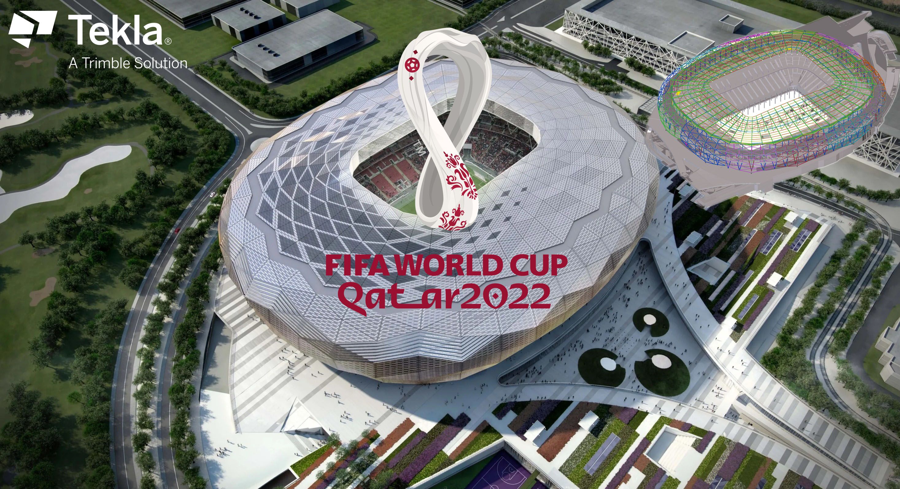
The Qatar Education City Stadium (QFS), located in Doha's Education City, Qatar's capital, is one of the venues for the 2022 Soccer World Cup and is designed to accommodate 44,000 people during the tournament. The project's structural form, a bowl-shaped concrete grandstand with a hub-and-spoke suspension steel roof, draws on Islamic architectural features, with the interior and exterior wrapped in translucent triangular panels that change color and pattern according to the sun's orientation and artificial lighting. The stadium uses a year-round cooling system to provide students, faculty, staff, and the local community with access to the stadium and surrounding facilities in Qatar Education City, encouraging generations of Qataris to achieve their fitness goals.
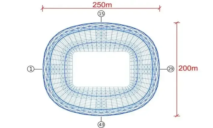
The total steel consumption of the project is about 7,000 tons, 750 tons of tension cables, and the maximum single weight of the members is about 32 tons. The steel roof is a gravity prestressed hub-and-spoke suspension cable diagonally braced primary and secondary beam structure. The structural plane is 250m long axis, 200m short axis, 50m gable height inside the pavilion, and the highest maximum overhanging span is about 61 m. The cable network system consists of outer ring beams, inner ring cables and radial cables between the inner and outer rings. The ring cable space into a saddle type, the plane projection into a ring, V-shaped diagonal braces to support the roof on the cable clamp node. In this project, Wuhan Dunxin is responsible for the deepening design of the main steel structure except the cable structure, and the deepening work is all done in Tekla.
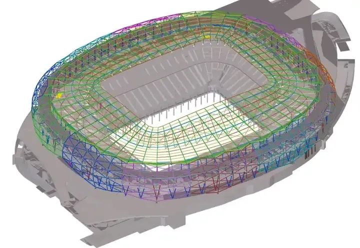
Tekla 3D model drawing of Education City Stadium
2. Structure and Node Introduction
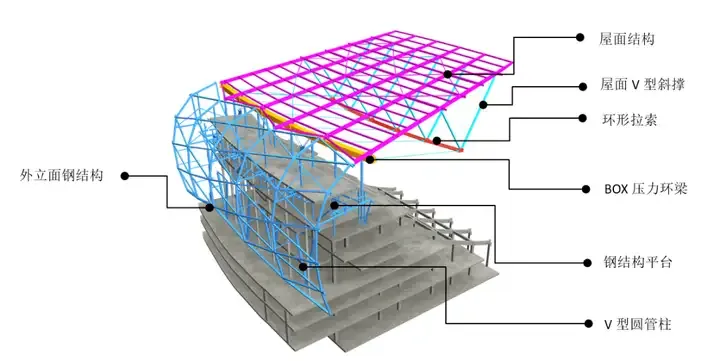
The steel structure system of the stadium is roughly divided into six parts, including the ground floor V-column support structure, platform level frame steel structure, facade curtain wall steel structure, roof support columns, spoke suspension system and roof steel structure. In the decomposition of the figure below, the V-shaped round tube columns support the steel platform on the outside of the stadium, the main steel platform is equipped with steel columns to support the steel structure of the facade curtain wall, and the roof steel structure is supported by the roof support columns and the hub-and-spoke suspension system, which constitutes the steel structure system of the whole stadium.
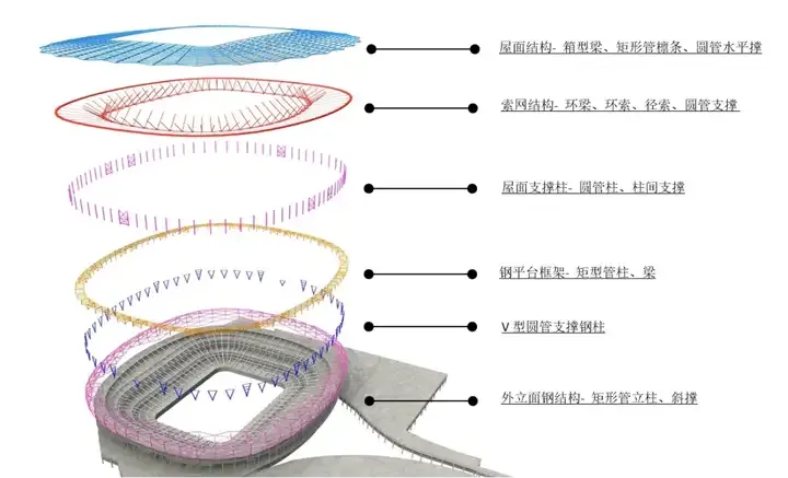
Stadium steel structure decomposition drawing
Typical Localized Drawing of Stadium Steel Structure
3. Deepening Design Focus and Solutions
3.1 Placement and positioning of space structures
Stadium type, mostly irregular or heterogeneous structure, key positioning points and bar positioning are extremely important. If the designer can provide a complete calculation model core can solve many primary problems. However, in the actual construction, most of the calculation and analysis model will be provided for reference only, the actual positioning according to the drawing to provide 3D coordinate positioning, and there will be rods do not intersect at one point or later adjustments. This requires us to locate and verify the accuracy and completeness of the design drawings.
V-Column, V-Column is the main column supporting the main steel frame near the outside of the arena, this part of the positioning is based on the 3D coordinates provided by the designer, and then combined with the height of the concrete floor to locate the V-column bottom elevation.
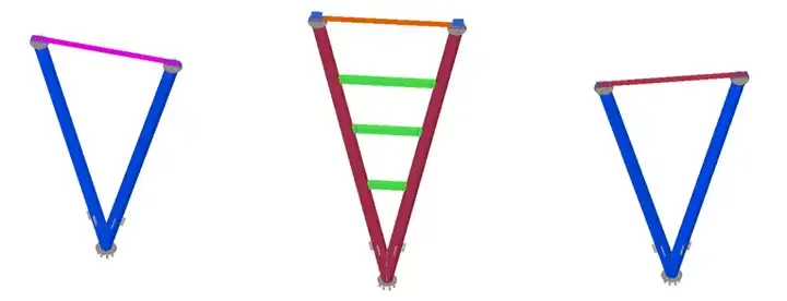
V-Column图
The structural steel frame section is defined by locating the circular axes and clarifying that the bars are concentric and uniformly distributed on the circular axes. The provided IFC concrete model was then utilized to define the outer edges of the steel supports.
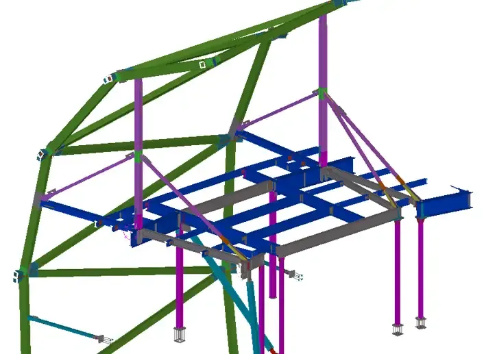
Steel Structure Platform Diagram
Facade part (facade curtain wall), according to the design of the overall coordinate system provided by the point control coordinates, organize data files. Then use the Open API to input the coordinates of the points and turn them into solid rods, calculate each triangular surface and adjacent triangular surfaces, and take the angular plane to locate the angle of rotation of the rods.
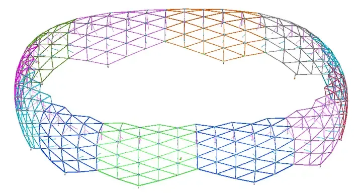
Facade curtain wall plan
There is a very important pressure ring in the hub and spoke suspension system, which has a horizontal pre-arch requirement to ensure that it can be contracted to the required position after tensioning, and here the model was modeled with both pre-arch and non-pre-arch as required. The actual processing in the factory is the model with pre-arch applied, and other connecting rods such as Roof and column rods are constructed in their final state.
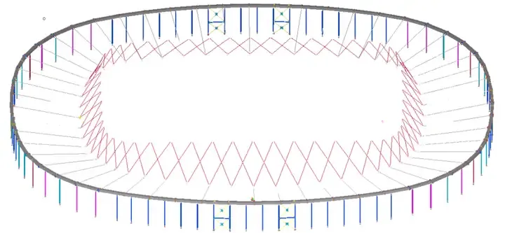
Pressure ring and roof support system diagram
Roof verified the analytical model provided by the design with the coordinates and placement criteria provided in the design drawings, and then directly imported the core model as a solid using Tekla to complete the positioning work.
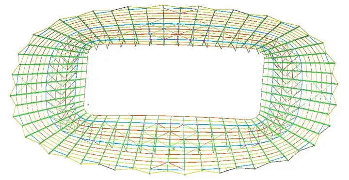
Nodal diagram of local steel joints of curtain wall of roof façade
3.2 node detail deepening
The steel structure platform is a two-dimensional rod with a large number of nodes, and we control the data of nodes of different types and specifications of rods through self-developed nodes in the form of Excel tables. Meanwhile, after modifying the node data by node calculation, we only need to modify the corresponding Excel data and refresh the modified node, which improves the convenience of node modification in the model. It can effectively front-load the modeling work to ensure the schedule when the schedule is tight and the node calculation fails to pass the audit.
One of the difficulties of this project lies in the connection nodes of the rectangular tubes on the Facade of the arena, where the external surface of the main structure requires very high precision, because both the interior and exterior are wrapped with semi-transparent triangular panels, whose colors and patterns change according to the sun's orientation and artificial lighting. However, the bars provided by the designer are all intersected at one point by the exterior control points to form different triangular surfaces, but all the triangular surfaces will not be coplanar, and the angle and rotation direction of each rectangular tube are different. Therefore, from the aesthetic considerations, the owner requires that the connecting end of the rods in the node range can not exceed the outer surface of the steel column by 2mm, and the exceeding part needs to be processed by localized cutting and then filling the triangular plate and then sanding.
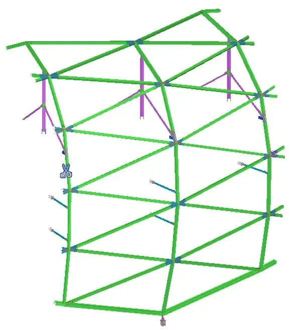
Partial view of façade curtain wall
In 3D space, it is difficult to find auxiliary surfaces and spatial points manually, and it is a huge workload to find the reference plane and then cut and supplement the triangular plate.TS can effectively play its advantages when there are rules to follow and the number of nodes is large. Based on Tekla Open API, we have developed a model plug-in node, which automatically calculates the size of the rectangular tube bull's leg end beyond the column surface, and then cuts and supplements the triangle plate according to the exceeding size. It perfectly meets the owner's needs and greatly improves productivity and reliability.

Detailed drawing of Facade welding nodes
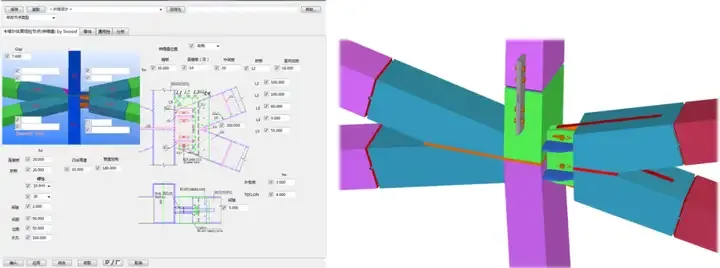
Facade Expansion Joint Node Detail Drawing
3.3 Auxiliary Drawing of Complex Rod Faces
When dealing with 2D rods, we have standard top or front views for reference, and the 2D dimensions can be clearly expressed. Of course, for 3D rods, we can also use the projection method to similarly label the dimensions. But the actual 3D rod superposition, end projection overlap, can not clearly and accurately express the required positioning dimensions, and the workload is large.
The following is the facade of the stadium facade (Facade) rectangular tube steel structure facade as an example to illustrate the auxiliary drawing of complex rod drawing. facade facade for a number of heterogeneous triangular composition, each rod is not in the same side of the column is also the use of a number of rods welded together and become. So we take a pole of the column as the reference surface, take the end up 1000mm as the reference point of origin, the length of the column for the reference axis, and then according to this as the reference point of the other 3D bull legs using 3D coordinates point labeling (using the form of tables to express, and at the same time can be generated for the factory to deal with the different needs of the data in the form of Excel documents). At the same time, in order to facilitate the production of factories, for the two-dimensional columns using dimensional labeling group positioning, local profile contact point positioning dimensions are still using two-dimensional dimensions, while increasing the local 3-dimensional diagram for reference.
The above approach meets the design intent and factory processing requirements, but the workload for drawing is huge and the deadline is tight. Therefore, we have developed different types of rods to assist the drawing of the surface. For the following rod main view dimensions automatically labeled, automatic processing of section view, 3D coordinates of the table automatically generated. With the auxiliary drawing, so that the greater liberation of productivity.
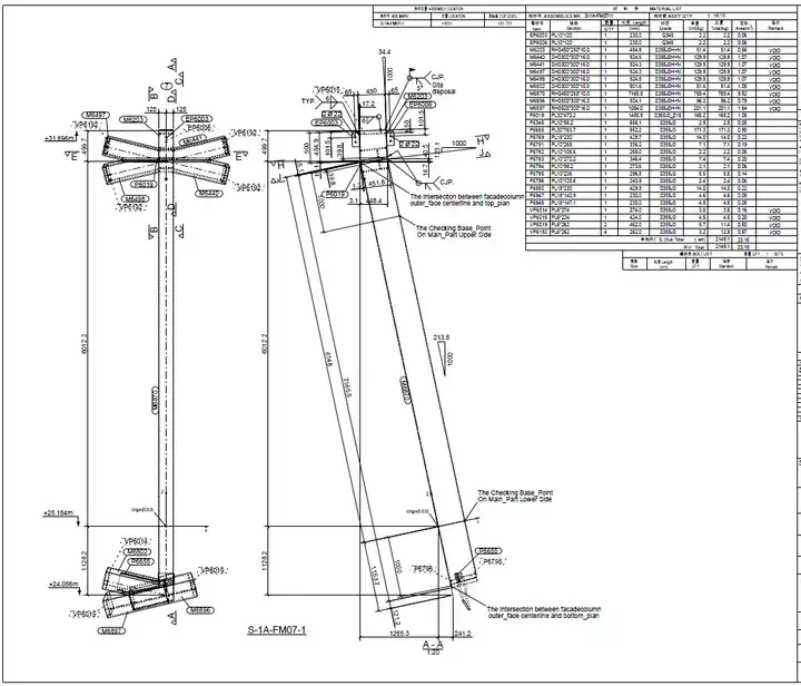
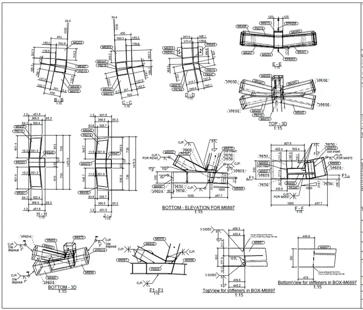
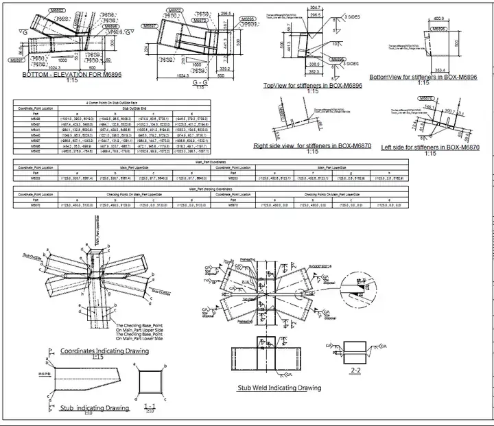
Sample Auxiliary Drawing
4. concluding remarks
Stadiums are mostly heterogeneous structures, but if you can find the similarity law between heterogeneous surfaces, through the programming interface (API) provided by Tekla, users can flexibly develop convenient plug-in tools according to their own needs, which greatly improves the efficiency and accuracy of modeling and drafting, and enhances productivity.

